Programming a Robot with Pick&Place
See the Robotics_PickAndPlace.project and Robotics_PickAndPlace_without_Depictor.project sample projects in the installation directory of CODESYS under ..\CODESYS SoftMotion\Examples.
The Robotics_PickAndPlace.project project requires the installation of the CODESYS Depictor package. This project visualizes the kinematics in a 3D animation. The project Robotics_PickAndPlace_without_Depictor.project shows a simplified form of the sequence in a visualization screen.
This chapter covers only the objects which are relevant for SoftMotion.
The example consists of a tripod, a rotary table, and a conveyor. The kinematics pick up a ring that is located on the rotary table. When picking up, the tool plate of the kinematics move synchronously with the rotary table. Then the ring is placed on a cone that is located on a conveyor belt. When placing, the kinematics move synchronously with the conveyor belt. Two buttons are located on the visualization screen for controlling the sequence. When you press the Auto button, the rings are set down automatically. Otherwise, the Play button appears for you to place the ring. | 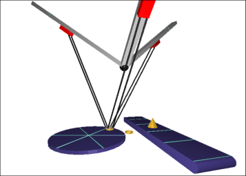 |
Structure of the project
CODESYS SoftMotion Controller
Axis group Tripod: The axis group defines the kinematics and the mapping to the individual axes Tripod1, Tripod2, and Tripod3.
DepictorCalculations (PRG), Environment (PRG), Ring (FB): Programs for controlling the complete sequence and visualization. These POUs are not relevant for understanding PLCopen blocks, except the definition of the product coordinate system (PCS_1 and PCS_2).
Robot (PRG): Program for controlling the movement sequences. A detailed description is located in the next paragraph.
Visualization: Animated visualization for clarifying the sequence.
Tripod1, Tripod2, Tripode3: Linear axes of the tripod.
DriveRotaryTable: Axis for the rotary table.
DriveConveyorBelt: Axis for the conveyor belt.
Structure of the Robot (PRG) sequential program
The Robot (PRG) program is run in cycles. At this time, the individual steps are performed depending on the state. At the end of a program, the calls of all used function blocks are ready for motion commanding.
The single axes of the tripod are activated (function blocks
pwA1,pwA2, andpwA3of typeMC_Power).CASE 0: Wait for the participating axes to be operational.CASE 10: Sets homing positions; in physical applications, homing is performed at this position (function blocksspA1,spA2, andspA3of typeMC_SetPosition).CASE 20: Placement of the machine coordinate system in the world coordinate system (function blocksetCoordof typeMC_SetCoordinateTransform).CASE 30: Enable the axis group (function blockenableof typeMC_GroupEnable.Wait for a response that the axis group has applied all values.
CASE 40toCASE 130: Pick&Place application: All movements are commanded possibly with a multiple instancesMC_MoveDirectAbsolute,MC_MoveDirectRelative, andMC_MoveLinearwhich are called in cycles. A rising edge at theExecuteinput of these POUs in each status leads to issuing a new motion command in which the outputbCommandAcceptedindicates the success of the process. A typical chain of commands results from interrogating this output before the next motion command.
Function Blocks: MC_TrackConveyorBelt and MC_TrackRotaryTable
The MC_TrackRotaryTable function block, which is called in the Ring function block, is used for determining the PCS_1 partial coordinate system. This coordinate system is set when a ring is placed on the rotary table.
The origin of the rotary table coordinate system RotaryTableOrigin is the midpoint of the rotary table. The Z-axis is the axis of rotation of the rotary table. The PCS_1 is rotated about the Z-axis of the rotary table coordinate system as a function of the input variable RotaryTable. Because the axis group moves in PCS_1, it follows the rotation of the table.
The behavior is similar to the MC_TrackConveyorBelt function block, which is called in the Cone function block. In this case, the PCS (PCS_2) follows the X-axis of the coordinate system ConveyorBeltOrigin.